- 您现在的位置:买卖IC网 > Sheet目录345 > NCP1910GEVB (ON Semiconductor)BOARD DEMO NCP1910DEMO-B-TLS
NCP1910
PFC Frequency Foldback
NCP1910 implements frequency foldback feature on PFC
section to improve the efficiency at light load. Thanks to
V in2 feed ? forward feature, the output power is proportional
to the (V CTRL ? V CTRL(min) ). The PFC frequency foldback
Vref
is hence done by comparing (V CTRL ? V CTRL(min) ) with
V fold , the voltage on Fold pin.
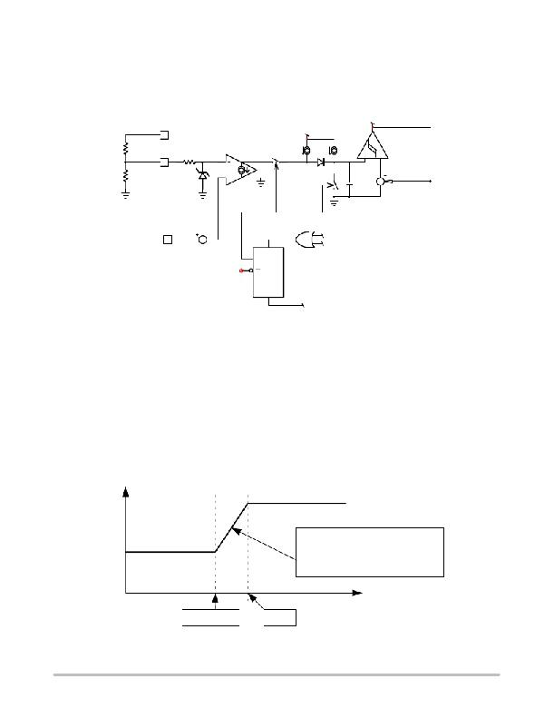
The simplified block diagram of PFC frequency foldback
feature is depicted in Figure 50.
PFCOSC
Vdd
Vfold
Vfold(max)
Ict(fold)
Ict
Ict(min)
“0” / ”1”
V PREF / 10%V PREF
Oscillator section
Vctrl
Grand Reset
Vctrl(min)
S
PFC BO
Q
Q
R
PFC OK
Figure 50. The PFC Frequency Foldback Block
Where:
? I Ct(min) limits the minimum operating frequency.
? I Ct and I Ct(min) provide the charging current for
oscillator and hence control the nominal operating
frequency.
? V fold determines the power level at which the
frequency foldback starts.
? I Ct(fold) steals the I Ct and hence reduces the
operating frequency according to the error
information between V fold and (V CTRL ?
V CTRL(min) ).
F sw(fold)
? The transient slope of frequency foldback vs. V CTRL
is fixed inside.
? V fold(max) is to limit the maximum power level of
frequency foldback, which is around 2 V typically.
The frequency foldback is disabled at startup, i.e. before
the PFCok signal in Figure 50 is asserted high.
The user can adjust the power level at which the frequency
foldback starts by adjust the resistor divider between V REF
pin and fold pin. Also, the frequency foldback can be
disabled by grounding fold pin.
The relationship between operating frequency and V CTRL
is depicted in Figure 51.
F sw
The slope is fixed internally.
The power level at which fre-
quency starts reducing is ad-
justable by modifying V fold .
V fold – 0.4
V fold
V CTRL ? V CTRL(min) T Power
Figure 51. The Relationship between Frequency and V CTRL
http://onsemi.com
26
发布紧急采购,3分钟左右您将得到回复。
相关PDF资料
NCP3418BMNR2G
IC MOSFET DRIVER DUAL 12V 10-DFN
NCP3418DR2
IC MOSFET DRIVER DUAL 12V 8-SOIC
NCP3420DR2G
IC MOSFET DRIVER DUAL 12V 8-SOIC
NCP3488DR2G
IC MOSFET DRVR DUAL 12V 8-SOIC
NCP5007SNT1
IC LED DRIVR WHT COMPACT 5TSOP
NCP5008DMR2
IC LED DRVR WHT BCKLT 10MICROSMD
NCP5010FCT1G
IC LED DRVR WHT BCKLT 8-FLIPCHIP
NCP5021MUTXG
IC WHITE LED DVR HV AMB 16-UQFN
相关代理商/技术参数
NCP1927DR2G
功能描述:功率因数校正 IC PFC AND FLYBACK CONTROLER RoHS:否 制造商:Fairchild Semiconductor 开关频率:300 KHz 最大功率耗散: 最大工作温度:+ 125 C 安装风格:SMD/SMT 封装 / 箱体:SOIC-8 封装:Reel
NCP1937A1DR2G
制造商:ON Semiconductor 功能描述:COMBO PFC & QUAZI FLYBACK - Tape and Reel 制造商:ON Semiconductor 功能描述:REEL / COMBO PFC & QUAZI FLYBACK
NCP1937B1DR2G
制造商:ON Semiconductor 功能描述:COMBO PFC & QUAZI FLYBACK - Tape and Reel
NCP1937BADAPGEVB
制造商:ON Semiconductor 功能描述:ADPTR 90W PFC+QR<10MW - Bulk 制造商:ON Semiconductor 功能描述:BOARD EVAL FOR NCP1937 制造商:ON Semiconductor 功能描述:Power Management IC Development Tools 90 W Adapter PFC+QR 10 MW Eval Brd
NCP21WB333
制造商:MURATA 制造商全称:Murata Manufacturing Co., Ltd. 功能描述:for Surface Mounting Application
NCP21WB333J03RA
功能描述:热敏电阻 - NTC 33K OHM 5%
RoHS:否 制造商:EPCOS 电阻:10 kOhms 功率额定值:150 mW 容差:2 % 端接类型:Radial 系列:B57703M 工作温度范围:- 55 C to + 125 C
NCP21WB333K03RA
功能描述:热敏电阻 - NTC 33K OHM 10%
RoHS:否 制造商:EPCOS 电阻:10 kOhms 功率额定值:150 mW 容差:2 % 端接类型:Radial 系列:B57703M 工作温度范围:- 55 C to + 125 C
NCP21WB473
制造商:MURATA 制造商全称:Murata Manufacturing Co., Ltd. 功能描述:for Surface Mounting Application
